GPIO Wiring
There are 3 “Sensor Pis”, and each will be attached to a GPIO button that will pass in signals to its Pi, as well as an LED strip and a Voltage Level Shifter, which toggles the monitor power when the RPi boots.
Repeat this process for each “sensor pi”.
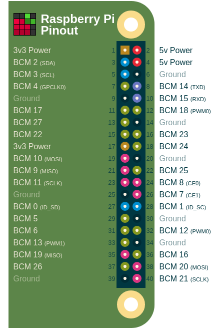
For reference, here is the standard pintout of the Raspberry Pi:
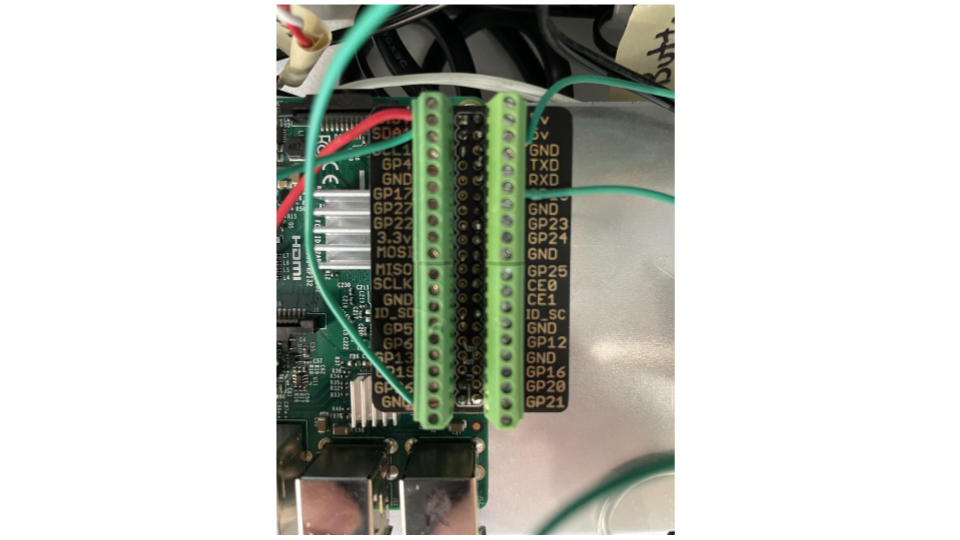
Images of the wiring can be seen below:
- The following pinout should be followed:
Board Pin #1, 3v3 Power –> Level Shifter Input Wire
Board Pin #3, BCM2/GPIO2/SDA –> Button Input Wire
Board Pin #6, GND –> Level Shifter Ground Wire
Board Pin #12, BCM18/GPIO18/PWM0 –> LED Signal Wire
Board Pin #39, GND –> Button Ground Wire